description: On-premises and colocation reference architectures for announcing your isp6 IPv6 PA assignment directly from your own data centres: a single-DC pattern with a CE router pair and eBGP, a multi-D
Reference Architectures: On-Premises and Colocation
Audience: isp6 members, network engineers, and platform architects who are announcing IPv6 PA space directly from their own data centre or colocation facility (rather than from a cloud provider's edge). This article assumes you control your own BGP-speaking edge equipment, have an ASN, and have completed isp6's standard activation flow (which produces the
inet6num,route6, and ROA records you need).Last updated: May 2026
1. What's in this article
Two on-premises / colocation reference architectures, plus a closing hybrid pattern:
- Architecture A: a single data centre running its own BGP edge. A pair of CE routers run eBGP with two upstream transit providers and an internet exchange route server. RPKI ROV is enforced locally. Inside the DC, a pair of L3 core switches feed a stateful firewall cluster fronting DMZ, application, and database VLANs, each with its own IPv6 /64.
- Architecture B: two data centres, each with its own /48 from a single /44. Independent eBGP sessions from each DC. iBGP via a route-reflector pair runs over a DCI (dark fibre, wavelength, or MPLS L3VPN). Each DC's /48 is advertised independently.
- Closing hybrid pattern: a sketch (no separate diagram) of how a /48 in your DC coexists with /48s in AWS, Azure, or GCP, all from the same isp6 /44.
Unlike the cloud articles, you own the BGP origin in these patterns: your own ASN appears in the global routing table, and the choices about route filtering, prefix lists, BFD, RPKI cache deployment, and DCI media are all yours. For the cloud-side BYOIP guides see AWS, Azure, and Google Cloud.
2. Architecture A: single-DC with a CE router pair
When to choose this: one production site, your own facility or a colocation cage, your own ASN, an HA pair of CE routers, and two or three upstream relationships (typically two transit providers plus an internet exchange).
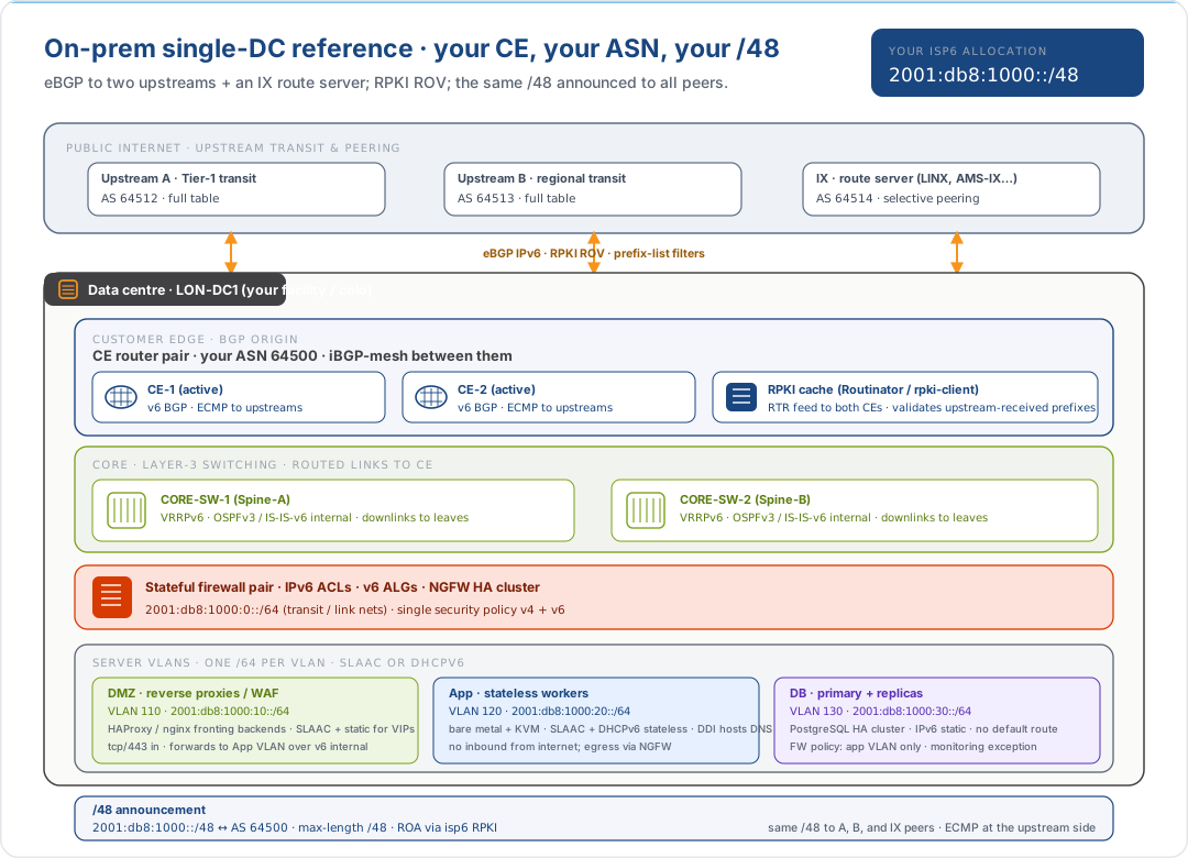
2.1 The BGP plane
| Layer | Role | Notes |
|---|---|---|
| Upstream transit (A, B) | Two independent transit providers, each receiving the full IPv6 table and your /48 | Pick providers in different ASes; ideally different physical paths to the DC |
| Internet exchange | Optional but recommended: a route server at LINX, AMS-IX, DE-CIX, etc. | Drops latency and cost for nearby networks; lets you reach content directly |
| CE router pair | Your edge, running BGP-4 with IPv6 address-family enabled | iBGP-mesh between them; ECMP across upstreams; BFD on all sessions |
| RPKI cache | An on-site Routinator or rpki-client deployment, feeding both CEs over RTR |
Lets you ROV-drop invalid prefixes received from upstreams; pin the local cache as valid for your own prefix so you don't depend on global RPKI convergence to reach yourself |
| ROA for your /48 + your ASN | Created and managed via your isp6 subnet dashboard | This is what makes your /48 ← AS 64500 announcement RPKI-valid for everyone else |
The CE pair is the only thing the global routing table sees from your site: the upstreams accept your /48 from you, RPKI ROV passes, and the /48 propagates worldwide.
2.2 The DC plane
| Layer | IPv6 carve | Notes |
|---|---|---|
| Transit / link nets | …:0::/64 (or shorter, /127 per link per RFC 6164) |
Between CEs, between CE and core, between core and firewall |
| DMZ | …:10::/64 |
Reverse proxies, WAFs, public-facing load balancers |
| App | …:20::/64 |
Stateless workers, container hosts, batch jobs |
| DB | …:30::/64 |
Stateful primaries and replicas; no default route off-site |
| Management | …:fe::/64 (typical) |
Bastions, jump hosts, RPKI cache, monitoring |
The same /48 → /56 → /64 convention from the cloud articles works at home too; the deeper carving discussion is in Planning Your isp6 Allocation.
2.3 Addressing the hosts
Three address-assignment modes coexist on most DC VLANs:
- SLAAC for general-purpose VMs and container hosts that don't care about their address;
- DHCPv6 (stateless) when you want the same hosts to receive DNS and other options from a managed server without giving up SLAAC for the address itself;
- Static for load-balancer VIPs, database primaries, and anything else that must keep the same address across reboots and rebuilds.
DHCPv6-PD (prefix delegation) is rare inside a single DC. It shows up if you delegate /60s out to subordinate L3 boundaries (hypervisor stacks, tenant networks), but most DC topologies prefer to centralise that in the IPAM tool.
3. Architecture B: multi-DC with iBGP and a DCI
When to choose this: two (or more) production sites, each capable of running the workload, with east-west replication between them. You want either active/active or active/standby across sites, and you want each site's /48 to be its own globally-routable advertisement so a site failure cleanly withdraws.
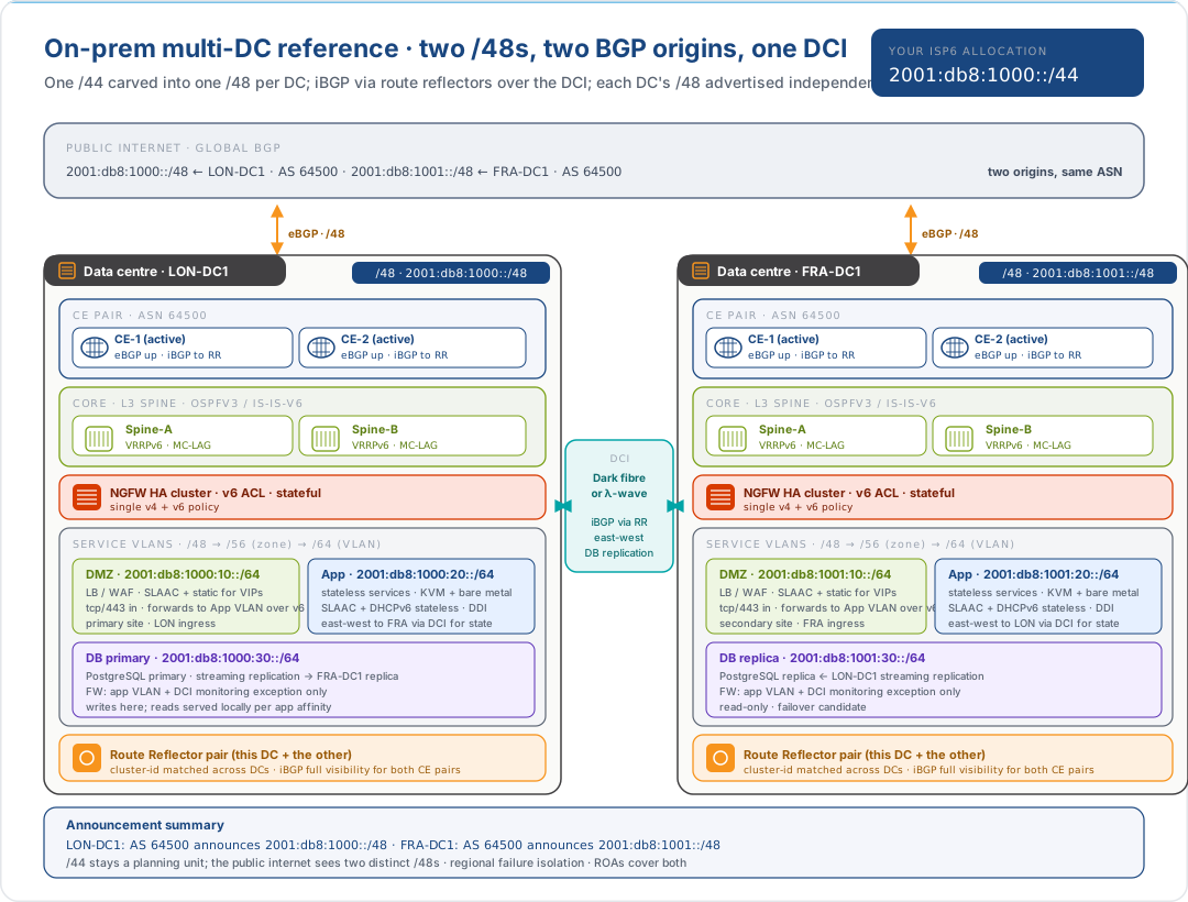
3.1 What the two /48s do
| /48 | Lives in | Announced from | Notes |
|---|---|---|---|
2001:db8:1000::/48 |
LON-DC1 | LON-DC1's CE pair, AS 64500 | Primary site for the workload |
2001:db8:1001::/48 |
FRA-DC1 | FRA-DC1's CE pair, AS 64500 | Secondary site; can be promoted on LON failure |
Both /48s come from the same /44 in the RIPE Database, and both ROAs are managed through your isp6 dashboard. The public internet sees two separate /48 advertisements with the same origin ASN, which is a perfectly normal anycast or multi-site pattern.
If you want a single anycast IPv6 service address across both sites, deploy that
inside the /48 of each site (e.g. 2001:db8:1000::1 in LON and
2001:db8:1001::1 in FRA) and add an anycast service prefix more specific than
/48 only if you are prepared to deal with global-routing-table filtering for
anything longer than /48, which usually means you should keep anycast within a
single /48 per site and use DNS-based routing to pick the site, not BGP.
3.2 The DCI plane
| Layer | Carries | Notes |
|---|---|---|
| Physical | Dark fibre, wavelength, or an MPLS L3VPN from a carrier | Bandwidth is your call; latency is what physics gives you |
| L3 over the DCI | A routed link or an OSPFv3 / IS-IS-v6 adjacency between the DC cores | Keeps the failure domain compact; don't bridge L2 across DCs unless you really mean it |
| iBGP via Route Reflector pair | Inter-DC reachability for both /48s and the inside-the-DC /56s | Two RRs (one in each DC, same cluster-id) eliminates an N×N iBGP mesh and survives one RR failing |
| East-west traffic | DB replication, batch jobs, service-to-service for affinity reasons | Encrypt at the DCI if it isn't already a private circuit you own end-to-end |
3.3 Why each DC is its own /48 and not a single /48 shared
This is the same point as in Sizing §5.1: splitting a /48 across two announcing origins is what the global routing table can see, but it is fragile: an announcement from FRA's /48-out-of-/48 plus an announcement from LON's /48-out-of-/48 would require longer-than-/48 prefixes that most networks will simply filter. The clean answer is one /48 per site, which makes /44 the natural size for multi-DC.
4. Closing pattern: hybrid: a /48 in a DC and /48s in public clouds
The most common real estate is neither pure cloud nor pure DC. It is a /48 in a DC for the data tier or for compliance reasons, plus one or more /48s in public clouds for elasticity, latency, or product reasons, all from the same isp6 /44.
The pattern is just the constellation diagram with the address columns populated:
| /48 from your /44 | Where it lives | BGP origin | Read |
|---|---|---|---|
2001:db8:1000::/48 |
Your DC | Your ASN | This article |
2001:db8:1001::/48 |
AWS eu-west-2 | AS 16509 / 14618 | Reference Architectures: AWS |
2001:db8:1002::/48 |
Azure uksouth | AS 8075 | Reference Architectures: Azure |
2001:db8:1003::/48 |
GCP global | AS 396982 | Reference Architectures: Google Cloud |
Four /48s in the routing table, four different BGP origins, one isp6 /44. Three operational properties of this pattern are worth pulling out. They are the things that make hybrid work:
- One source of truth. Every one of those /48s authorises its origin through a ROA, and every ROA lives under the isp6 RPKI certification authority. Adding AWS to an estate that previously announced from your DC is one ROA change in the isp6 dashboard, not a new RIR engagement.
- Independent failure domains. The DC /48 can be withdrawn (carrier failure, facility issue, planned maintenance) without touching the cloud /48s. The cloud /48s can be deprovisioned (cloud-account closure, region exit) without touching the DC /48.
- Private east-west, public north-south. Inter-/48 traffic should travel over private interconnects: DX / ExpressRoute / Cloud Interconnect from the DC to each cloud, and the same DCI from Architecture B between DCs. The public internet is for client traffic, not service-to-service.
The hybrid case is also the practical answer to "what if I'm not sure I want the cloud forever?", your /48 in the DC is the long-term ownership story, and the cloud /48s come and go (or move between clouds) over the life of the allocation without ever needing a renumber on the consumer side.
5. On-prem-specific design rules
Specifics that shape these architectures and that don't apply on AWS, Azure, or GCP:
- You own the ASN and the ROA. isp6 publishes a ROA covering your /48 (or /44) for your ASN, but the BGP configuration on your CE pair is yours. Get the prefix-list and AS-path filter direction right: announce only your /48(s), and accept only what you should from each upstream.
max-lengthin the ROA matters. Set it to /48; allowing longer (e.g. /128) opens the door to a leak that becomes RPKI-valid for an attacker. See RFC 7454 §6.- BCP 38 / RFC 2827 on the IPv6 path. Drop packets sourced from inside your /48 at the upstream ingress; drop packets sourced from outside your /48 at your egress. Trivial to forget when turning on a new transit.
- BFD on every BGP session. Sub-second failover between CE-A and CE-B and to each upstream is what makes the HA pair actually highly available.
- OSPFv3 or IS-IS-v6 for the IGP. Either is fine; pick one and use it for both v4 and v6. Don't run separate routing instances per family if you can help it.
- DHCPv6-PD is rare in the DC, common at the customer edge. Most DC server fleets use SLAAC with static reservations for VIPs.
- Document the /56-per-zone carving in IPAM. A DC that lives long enough will sprout more VLANs than you planned. Reserve generously and apply the bisection method when handing out /56s to new zones.
6. What's intentionally out of scope
| Topic | Where to look |
|---|---|
isp6 onboarding, inet6num, route6, ROA management |
Planning Your isp6 Allocation and your isp6 subnet dashboard |
| Sizing decision (/48 vs /44) | Sizing: /44 vs /48 |
| Cloud-side BYOIP mechanics | AWS, Azure, Google Cloud |
| Physical, power, cooling | Your facility/colo operator's runbook |
| Detailed BGP-tuning, route policy, MED / local-pref | RFC 7454 + your vendor's BGP guide |
| Server-side DNS, IPAM (DDI) selection | A separate operations decision |
7. Further reading
Other reference architectures in this series
- Reference Architectures: An Overview: start here for the cross-provider terminology and the deployment-mode decision aid
- Reference Architectures: AWS
- Reference Architectures: Azure
- Reference Architectures: Google Cloud
isp6 knowledge base
- Sizing: /44 vs /48: which size to order
- Planning Your isp6 Allocation: internal carving and the bit-budget method
- IPv6 Prefix Chart: quick prefix-size reference
- Stop Thinking in IPv4: the IPv4 reflexes (NAT, conservation) to unlearn before designing a DC v6 plane
- Digital Sovereignty: context for choosing on-prem over (or alongside) cloud
RIPE NCC and IETF
- RFC 6164: Using 127-Bit IPv6 Prefixes on Inter-Router Links
- RFC 6177: IPv6 Address Assignment to End Sites
- RFC 7454: BGP Operations and Security
- RFC 8210: RPKI to Router Protocol (RTR), v1
- RIPE-738: IPv6 Address Allocation and Assignment Policy
Tooling and operational references
- Routinator (NLnet Labs RPKI validator)
- rpki-client (OpenBSD RPKI validator)
- PeeringDB: discover IX presences and peering partners
This document is provided for informational purposes. Protocol specifications and cloud provider behaviour are subject to change. Consult the linked RFCs and vendor documentation for authoritative, up-to-date information before making architectural decisions.